- Focus
- Power and machines
- Main tools
- Multisim, Oscilloscope, Function generator, Digital multimeter
- Headline result
- Laboratory experiments: 7
A library of simulated circuits: AC and DC theory, RLC and resonance, filters, op amps, amplifiers, and digital adders up to an ALU.
Problem
Circuit theory only sticks when you verify it. The goal was to check hand calculations against simulation and against bench measurements for a wide set of circuits.
What I built
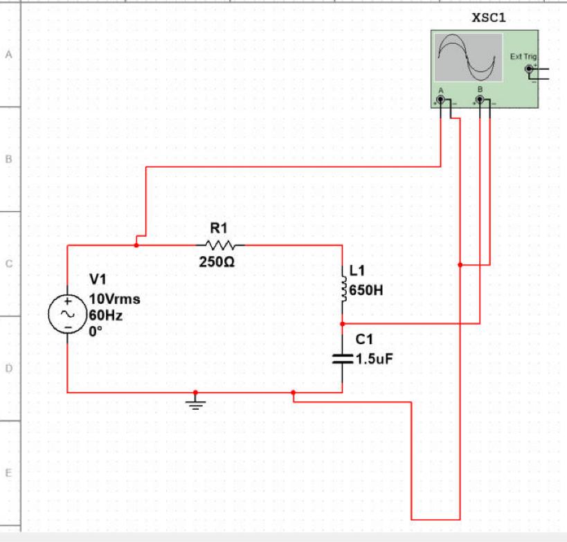
- AC with resistive and inductive loads, series and parallel RC, RL and RLC circuits, and resonance, checked against calculated reactance, impedance and resonant frequency.
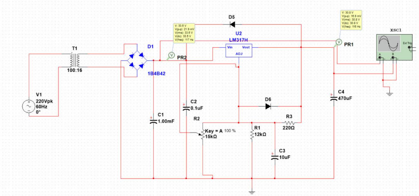
- Low-pass and high-pass filters, inverting and non-inverting op amps, and class A and class B amplifiers.
- Half and full adders with truth-table checks, ripple-carry delay analysis, and a synchronous adder-based counter.
- A seven-experiment AC/DC laboratory workbook using function generators, oscilloscopes and multimeters.
Tools and standards
- Multisim
- Oscilloscope
- Function generator
- Digital multimeter
Result
Circuit behaviour was verified against theory for each experiment. The workbook covers seven laboratory experiments.
| Metric | Value | Source |
|---|---|---|
| Laboratory experiments | 7 | Author's engineering portfolio (PDF) |
Visuals
Sources
- Author's engineering portfolio (PDF)
- Author's coursework and project files